How do the frequency converter and the PLC "hook up" together?
In many cases, the inverter needs to be matched with the PLC, one is to meet the needs of control, and another is to expand the function of the inverter, realize the requirements of multi-segment speed control, which can not only realize the predetermined function, but also simplify the wiring and reduce the failure rate.
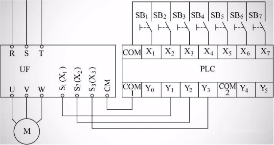
Frequency converter has a lot of switching volume terminals, such as forward turn, reversal and multiple speed control terminal, do not use PLC, as long as the terminal switch and the terminal function can be preset.
When PLC is used to control frequency converter, if PLC controls frequency conversion by switching volume, it is necessary to connect the switching volume output terminal of PLC with the switching volume input terminal of frequency converter. In order to detect some states of the frequency converter, the switching volume output terminal of frequency converter should be connected with the switching volume input terminal of PLC.as illustrated in following figure:
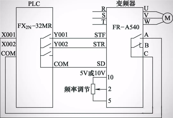
When the PLC internal program is running, the Y001 terminal is closed, the inverter STF terminal is closed, the inverter converter starts the motor to turn forward, and the adjusting potentiometer can change the input voltage of the terminal 2, thus changing the output frequency of the inverter. When the inverter fails, terminals A and C are closed, terminal PLCX001 terminal is closed, and the input state of X001 terminal is ON.
Here need to pay attention to, is the public choice, COM is a broad public end, can be high potential, but also can be low voltage, but GND on the frequency converter is a narrow sense of public end, refers to the power negative, is only low potential, in the configuration of frequency converter and PLC connection, especially pay attention to, because PLC COM can be high potential, but also can be low potential.
Take an example of PLC realizing motor forward and reverse frequency modulation, as shown in the figure below:
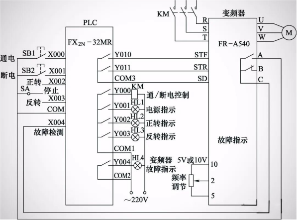
This is very simple, KM controls the converter to power, drop point, X002 closed, Y010 closed access, forward turn; X003 closed, Y011 closed access, reverse. The potentiometer changes the voltage input of the 2 to achieve the frequency modulation. The frequency converter switching capacity output A, C is closed as A fault, connected by X004, no matter positive or reverse, as long as the fault, that is, stop. Y 001 to Y 004 indicate the output of 4 states.
About inverter parameter setting, are relatively simple, external control, frequency mode, control mode, motor parameters, parking mode, deceleration time, upper and lower limit frequency, relay output, etc., conventional setting, if to meet the specific function, also need to set the specific function of inverter parameters, such as frequency converter protection, load type, low frequency compensation, anti electric, etc., is not listed one by one.
This article says so some, a simple list of the frequency converter and PLC connection and implementation process, a simple understanding, complex can be gradually simplified to understand, nothing more than to add some control, to achieve some established functions.








Please first Loginlater ~